
 Tel:+86-23-67956606
 Email:

The Design of the Drum with Lebus Groove
The drum is an important component of the winch. According to the number of winding layers of the wire rope on the drum, it can be divided into single-layer winding and multi-layer winding. For multi-layer winding, traditional drums often suffer from problems such as chaotic arrangement of wire ropes and increased friction due to the increase in the number of layers, which makes them prone to damage. However, the design of a drum with Lebus groove can effectively solve this problem.
Design of the Wall Thickness of the Drum with Lebus Groove
When determining the wall thickness of the drum with Lebus groove, it should be noted that in the case of multi - layer winding, when the first - layer wire rope is wound, the tension of the wire rope coils in the first - 1 layer of the first layer that was wound earlier will all decrease (affected by the deformation of the drum wall and the deformation of the wire rope coils). This will affect the compressive stress of the drum wall. In the case of multi - layer winding, if these elastic effects are not considered and it is assumed that the tensile forces of the wire ropes in all layers compress the drum wall, the calculated wall thickness will be too large. Designers should pay attention to this.
Design of the Drum with Lebus Groove
1. Design of the Rope Grooves of the Drum with Lebus Groove
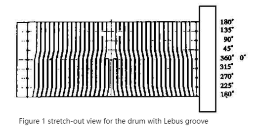
Figure 1 shows the stretch-out view of the drum with Lebus groove. The radius of the rope groove arc is R, and the distance between the rope grooves is t.
From the figure, it can be seen that the line between 45 ° to 0 ° and 225 ° to 180 ° is a spiral groove with a width of 1/2t, while the remaining segments are circular grooves.
2. Design and Function of Left and Right Retaining Rings for the Drum with Lebus Groove
The the Drum with Lebus Groove not only requires a special angle of its rope groove, but also requires retaining ring devices at both ends to allow the steel wire rope to enter the second layer and wrap upwards in an orderly manner.
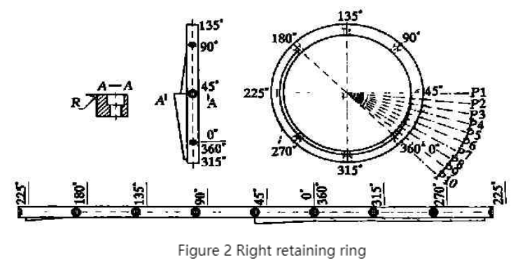
Figure 2 shows the right retaining ring, where the divisions correspond one-to-one with the drum (the left and right retaining rings have the same shape and function).
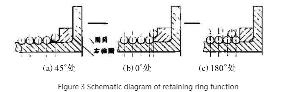
Figure 3 is a schematic diagram of the function of the retaining ring. As can be seen from Figure 2 in combination with the right end of the developed drawing of the drum with Lebus groove, the wire rope should complete the climb from the height of the inner layer to the height of the second layer between 45° and 0°. This requires that the height at the position of the retaining ring P1 is equal to the outer diameter of the drum, and the height at the position of P10 is the height of the second layer of the wire rope. The section from P1 to P10 is a uniformly ascending convex platform for this height, so as to ensure that the wire rope can rise smoothly to the height of the second layer (see Figures 3a and 3b). Since the rope groove of the drum is a zigzag line (with a bend of half of the rope groove pitch) in the section between 45° and 0°, the width of the uniformly ascending convex platform of the retaining ring at 45° is one rope groove pitch. When it is at 0° of the zigzag line, there is only half of the rope groove pitch. Only in this way, when the retaining ring is installed on the drum, it will not block the wire rope of the inner layer in the sections between 45° and 0°, as well as the sections at 315°, 270° and 225°. Because the wire rope starts to climb from 45° and reaches the height of the second layer at 0°, then runs at the height of the second layer and passes through the angles of 315°, 270° and 225°. In this process, there is only half of the rope groove pitch between the vertical surface of the retaining ring and the wire rope of this layer. Therefore, there must be an R-shaped rope groove between the convex platform of the retaining ring and the vertical surface of the retaining ring. From 225° to 180°, the rope groove of the drum and the convex platform of the retaining ring form a zigzag line again (with a bend of half of the rope groove pitch). At this time, the distance between the wire rope of this layer and the vertical surface of the retaining ring gradually decreases from half of the rope groove pitch to zero. At this moment, the wire rope naturally crosses the wire rope of the inner layer on the zigzag section and enters the groove formed by the wire rope of this layer, thus completing the reverse movement of the wire rope (see Figure 3c).
This special kind of retaining ring is set at both ends of the drum with Lebus groove, which ensures that the wire rope can rise smoothly to the second layer, and makes the wire rope turn back and start the orderly winding of the second layer.
Advantages of the Design of the Drum with Lebus Groove
The design of the drum with Lebus groove has the advantage that there is no extrusion between the ropes, which can effectively reduce the wear of the wire rope and prolong the service life of the wire rope. After the first layer is wound, the wire rope can rise smoothly to the second layer through the retaining rings at both ends, ensuring smooth opening and closing operations. Then, it starts the neat and orderly reverse winding of the second layer. In this way, it can be wound to the third layer, the fourth layer and so on. The production cost and the weight of the unit are only slightly higher than those of the ordinary drum.