MARINE & OFFSHORE EQUIPMENT
- Dredging Equipment
- Marine Deck Machinery
-
Marine Mooring Equipment
-
Marine Anchor
- AC-14 HHP Anchor
- Admiralty Anchor
- Beldt Stockless Anchor
- Bruce Anchor
- Spek Anchor
- Danforth HHP Anchor
- Delta High Holding Power Anchor
- GB11579-89 Light Weight Anchor
- Hall Anchor
- High Holding Power Mastrosov Anchor
- Hot Dip Galvanized Anchor
- Japan Stock Anchor
- JIS Stockless Anchor
- Pool Anchor
- Single Fluke Anchor
- Stainless Steel Anchor
- Stevpris MK5 Anchor
- Stingray Anchor
- US Navy Stockless Anchor
-
Marine Anchor Chain
-
Marine Shackle
- Kenter Shackle
- D Type Joining Shackle
- Pear Shaped Shackle
- Anchor Swivel Shackle Type A
- Anchor Swivel Shackle Type B
- Buoy Shackle Type A
- Buoy Shackle Type B
- C Type Detachable Connecting Link
- D Shackle
- Forelock Shackle
- Anchor Chain Swivel Group
- Straight Shackle
- Anchor Shackle
- Marine Triangle Plate
- Anchor Chain Swivel
- Anchor Chain Joining Shackle
- Anchor Chain End Shackle
- Slim Kenter Shackle
-
Chain Chaser
-
Marine Bollard
-
Marine Chock
-
Marine Fairlead
-
Marine Chain Stopper
-
Marine Mooring Reel
-
Marine Towing Bracket
-
Mooring Rope
-
Marine Towing Hook
-
Marine Shark Jaw
- Marine Fender
-
Marine Buoy
- Marine Floating Pontoon Dock
-
Marine Anchor
- Aquaculture Equipment
- Marine Outfitting Equipment
- Marine Propulsion System
-
Marine Painting
-
Marine Auxiliary Machinery
- Marine Air Compressor
- Marine Air Receiver
- Marine Sewage Treatment Plant
-
Marine Diesel Generator Set
- Marine Oil Water Separator
- Ballast Water Management System
- Marine Hydrophore
- Marine Calorifier
- Seawater Desalination Plant
-
Marine Oil Separator
- Marine Fuel Oil Supply Unit
- Marine Heat Exchanger
-
Marine Hot Well Unit
-
Marine Incinerator
-
Marine Boiler
-
Marine Valve
- JIS Marine Valve
- DIN Marine Valve
- ANSI Marine Valve
- GB Marine Valve
- CB Marine Valve
- CBM Marine Valve
-
Marine Gate Valve
-
Marine Globe Valve
-
Marine Angle Globe Valve
-
Marine SDNR Valve
-
Marine Angle SDNR Valve
-
Marine Check Valve
-
Marine Storm Valve
-
Marine Butterfly Valve
-
Marine Quick Closing Valve
-
Marine Fire Valve
-
Marine Self Closing Valve
- Marine Valve Accessories
-
Marine Pump
- Marine Centrifugal Pump
- Marine Screw Pump
-
Marine Gear Pump
-
Marine Vortex Pump
-
Marine Ejector Pump
-
Marine Diaphragm Pump
-
Marine Piston Pump
-
Marine Fire Pump
-
Marine Emergency Fire Pump
-
Marine External Fire Pump
-
Marine Ballast Water Pump
-
Marine Fuel Pump
-
Marine Lubricating Oil Pump
-
Marine Bilge Pump
-
Marine Sewage Pump
-
Marine Domestic Water Pump
-
Marine General Pump
-
Marine Cargo Oil Pump
-
Marine Hand Pump
- Marine Pump Parts
- Marine Life-saving Equipment
- Fire-fighting Equipment
- Marine Cable
- Marine Electrical Equipment
- Marine HVAC
-
Labour Protection Appliance
- Marine Decorative Material
-
Marine Anode
- Marine Pipe Fitting & Flange
- Marine Instrument
- Ship Building Equipment
INDUSTRY EQUIPMENT
- Hoisting Equipment
- Welding Machine & Material
-
Cutting Machine
- Container Securing Fitting
- Link Chain
- Container & Storage Equipment
-
Diesel Generator Set
- Other Equipment and Tools
- Petrochemical Equipment
- Fiber Reinforced Plastics
- Polymer Materials
- Environmental Protection Series
- Geo-products and Building Materials
- Metal Mesh
- Steel Grating
-
Earthwork Teeth
-
Turnbuckle
STOCK LIST
Contacts
 Tel:+86-23-67956606
FAX:+86-23-67956622
 Email:manager@cqhisea.com
Working Time: 9:00--17:00
Working Day: Monday to Friday Website: www.cqhisea.com


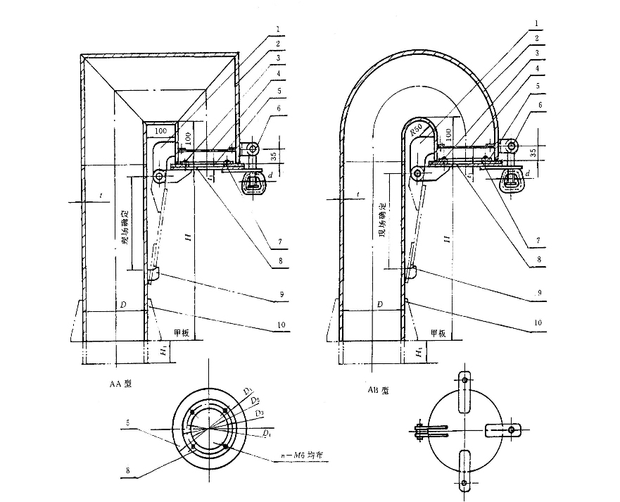
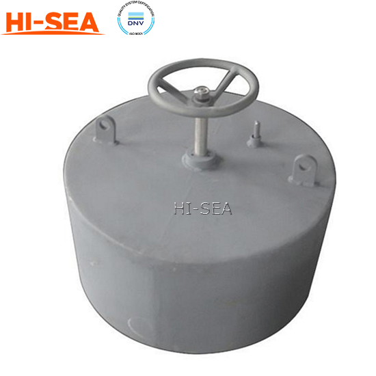
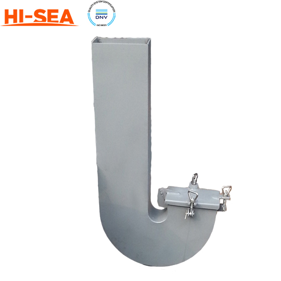
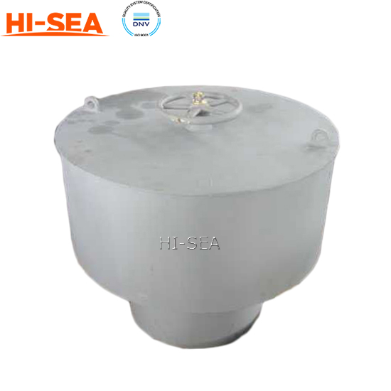
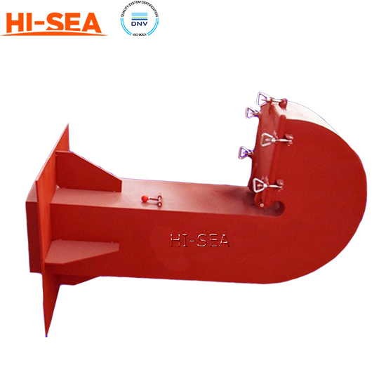
Gooseneck Air Ventilation
Gooseneck Air Ventilation
Introduction:
Gooseneck air ventilation is a type of air ventilation system that utilizes a flexible gooseneck duct to provide targeted airflow in specific areas. It is commonly used in various settings such as industrial facilities, laboratories, workshops, and commercial spaces where localized ventilation is required.
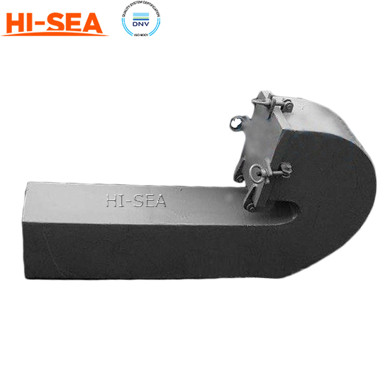
The gooseneck design refers to the flexible and adjustable nature of the duct. It consists of a rigid section at one end and a flexible, bendable section resembling a gooseneck, hence the name. This flexibility allows for easy positioning and directing of the airflow to specific areas, providing effective ventilation exactly where it is needed.
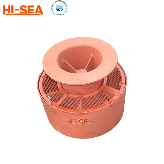
Gooseneck air ventilation systems are typically connected to an air extraction system, such as a fan or an HVAC (Heating, Ventilation, and Air Conditioning) system. The fan or HVAC system creates negative pressure that draws air from the surrounding space through the gooseneck duct, effectively capturing and removing airborne contaminants, fumes, or odors from the targeted area.
One of the key advantages of gooseneck air ventilation is its versatility. The flexible gooseneck duct can be easily adjusted to direct airflow in different directions, angles, or heights, allowing for precise control over the ventilation process. This feature makes it particularly useful in situations where fixed or rigid ducts may not be suitable or practical.
Gooseneck air ventilation systems are often equipped with additional features to enhance their functionality. These can include adjustable dampers to control airflow rate, filters to capture particulate matter, and noise reduction mechanisms to minimize operational noise.
Overall, gooseneck air ventilation offers an efficient and customizable solution for localized ventilation needs. By providing targeted airflow, it helps maintain air quality, remove contaminants, and ensure a safer and more comfortable environment in specific areas of use.
Specification
DN
airduct
Cover
padding
press plate
D
t
D1
t1
D1
D2
D2
D3
D4
100
108
4
118
6
118
48
48
78
63
114
6
124
8
124
54
54
84
69
8
150
159
4.5
170
6
170
100
100
130
115
168
6
178
8
178
108
108
138
123
8
200
203
6
213
6
213
143
143
173
158
219
6
229
8
229
159
159
189
174
8
250
245
6.5
255
6
255
185
185
215
200
273
6.5
283
8
283
213
213
243
228
8
300
299
7.5
309
6
309
239
239
269
254
325
7.5
335
8
335
265
265
295
280
9