
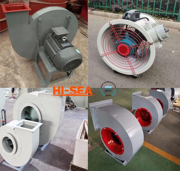
Navy Centrifugal Fan
1. General
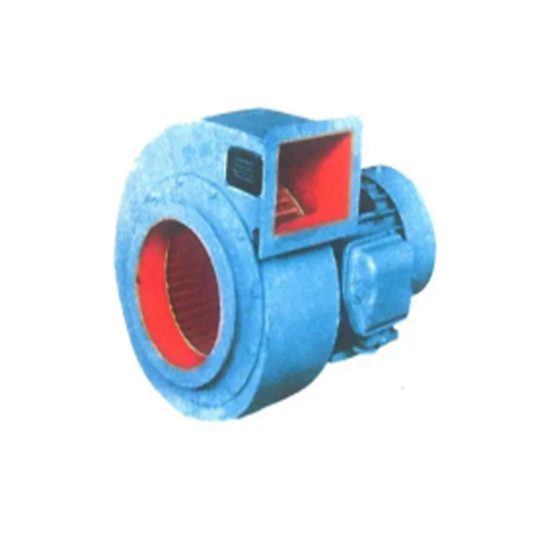
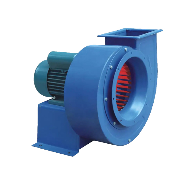
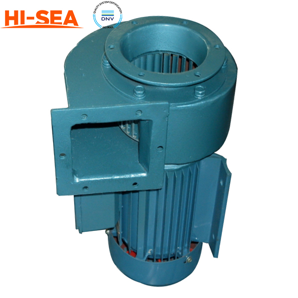
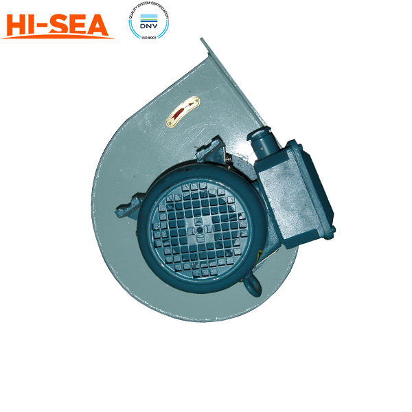
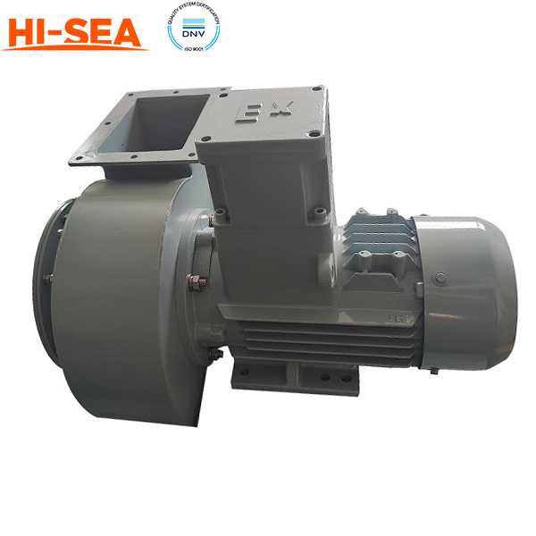
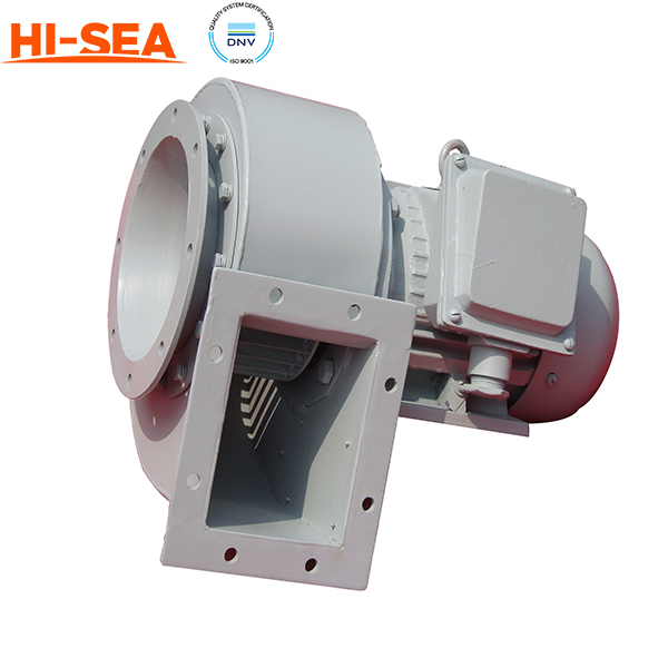
Navy centrifugal fans are widely used in various naval applications such as ventilation, air conditioning, and air circulation systems. These fans are designed to be durable, reliable, and resistant to harsh marine conditions, and they use centrifugal force to move air or gas through a system.
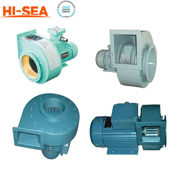
Navy centrifugal fans come in a variety of designs and configurations, including single-stage, multi-stage, and variable-pitch fans. The materials used in the construction of Navy centrifugal fans are typically selected for their durability and resistance to corrosion and other harsh marine conditions. Common materials include stainless steel, aluminum, and fiberglass-reinforced plastics.
2. Features
High efficiency: Marine centrifugal fans are designed to provide efficient airflow and ventilation to various parts of a marine vessel, ensuring the proper circulation of air and preventing the buildup of potentially hazardous gases.
Durable construction: These fans are typically constructed from high-quality materials that are resistant to corrosion, rust, and other environmental factors. This ensures the fan's longevity and reduces the need for frequent maintenance and repairs.
Low noise levels: Marine centrifugal fans are designed to operate at low noise levels, ensuring that the fan doesn't create excessive noise pollution or interfere with onboard communication.
High performance: These fans are designed to operate at high speeds, providing powerful airflow even in challenging environments.
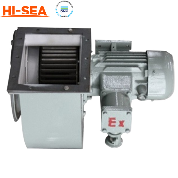
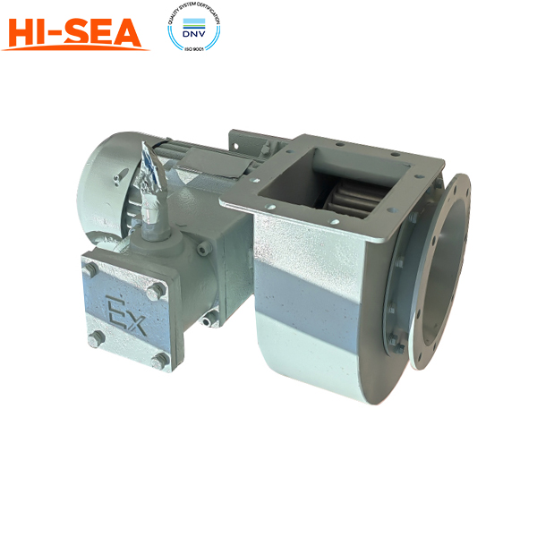
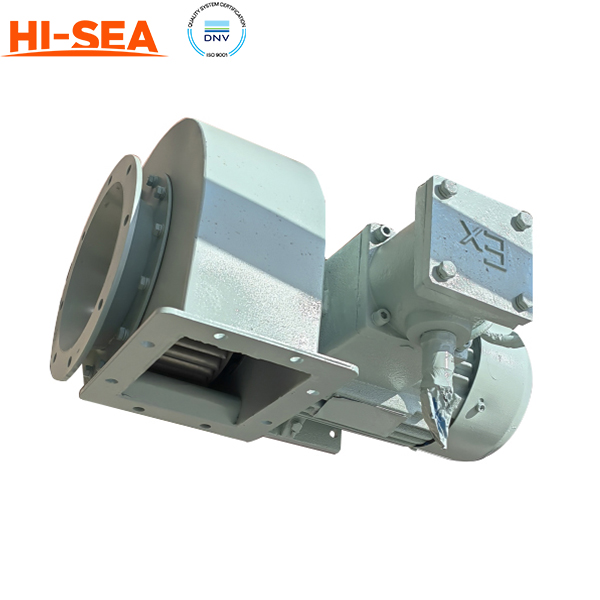
Safety: Marine centrifugal fans are often designed to be explosion-proof and meet strict safety standards to prevent accidents and ensure the safety of crew members and passengers.
Flexible installation: These fans can be installed in a variety of locations and configurations to suit the specific needs of the marine vessel, making them a versatile solution for ventilation and air conditioning.
Configuration material selection:
|
Part Name |
Texture of Material |
Characteristic |
|
Casing |
Carbon Steel |
1.The melting process is relatively simple and the cost is reduced; 2.Good pressure machining performance, cutting performance and comprehensive mechanical performance |
|
Impeller |
Aluminium Alloy |
1.Strong plasticity, light weight and high strength; 2.It has strong air tightness, water tightness, heat insulation and sound insulation; 3.Corrosion resistance and long service life |
|
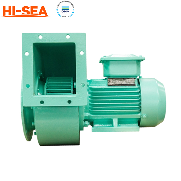
Electric Machinery |
|
Finished marine motor with low noise, low vibration and high protection grade |
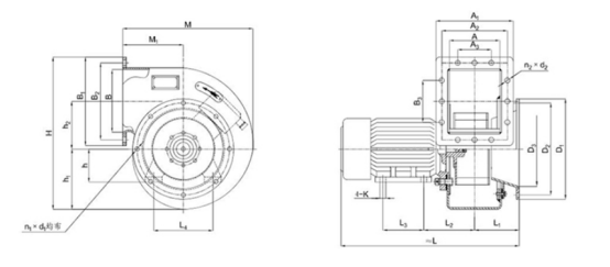
Drawing:
The specific differences are as follows:
|
Product of other low-quality suppliers |
Product of our factory |
|||
|
|
|
|||
|
Casing |
Low-quality suppliers |
Adverse consequences |
Our factory |
Use effect |
|
Select sheet steel |
Easy to deform and greatly shorten the service life |
Strictly adopt national standard thickness steel plate |
Not easy to deform, durable |
|
|
Electric Machinery |
In order to reduce costs, motors produced in small workshops are used |
If the power fails to reach the rated power, the fan will start for a long time or even fail to start |
Adopt Marine Standard Motor |
Immediately the fan will starts quickly, operates stably and has a long service life |
|
Coil |
In order to reduce the cost, aluminum wire or copper clad aluminum wire is selected as the coil |
Not durable |
|
|
|
Manufacturing process |
Manual cutting |
Manufacturing accuracy does not meet the requirements, and the product cannot meet the rated performance |
NC plasma cutting is adopted, and the manufacturing is strictly in accordance with the drawing size |
High precision, good molding, stable operation, fully reaching the rated performance parameters |
|
Model selection fails to meet the requirements |
The air pressure and air volume cannot meet the use it needs |
Model selection in strict accordance with requirements |
Fully meet the suction and delivery air volume required by the actual system |
|
Our inventory:
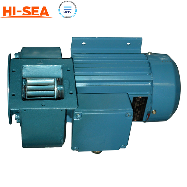
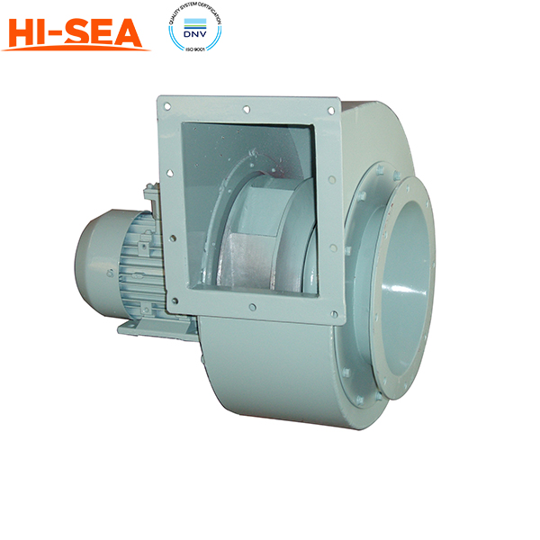
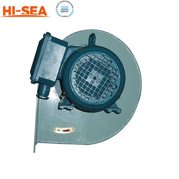
1. The ventilator is generally of horizontal and electric direct connection structure, and can also be made into a built-up structure when necessary;
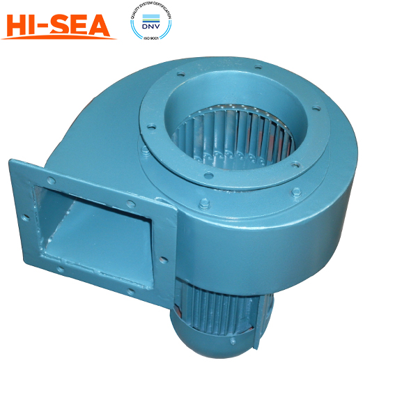
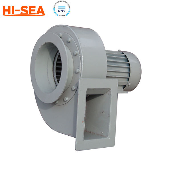
2. The fan inlet collector is connected with the casing through the cover plate, and the impeller is directly installed on the motor shaft;
3. The casing is connected with the motor through the connecting disc;
4. The motor is installed on the motor base;
5. The position of the system pipeline shall be set out or adjusted according to the actual position of the inlet and outlet of the ventilator, and excessive dislocation, tension or compression of the inlet and outlet flexible pipe shall be avoided;
Precautions for installation:
1. Know the sample of the fan before installation, and be familiar with the specification, type, impeller rotation direction and air flow in and out direction of the fan;
2. Conduct a comprehensive inspection of all components before installation: check whether the impeller is scratched, whether the accessories are complete, and whether the connections of all components are fastened. Pay special attention to check the fan blade. If it is damaged or deformed due to transportation, wait for the fan blade to be repaired before installation;
3. The air duct connecting the inlet and outlet of the marine fan should have a separate support, and it is not allowed to add the weight of the duct to the components of the fan;
4. During installation, attention should be paid to the horizontal position of the fan. The joint surface between the fan and the foundation and the connection of the air outlet pipe should match naturally, and forced connection is not allowed;
5. After the installation of the marine fan, pull the impeller by hand or lever to check whether it is too tight or collided, and whether there are objects that hinder the rotation. The test run can be carried out only after there is no abnormality;
6. The exposed part of the marine fan transmission device shall be equipped with a protective cover (provided by the user). If the fan inlet is not connected to the pipe, it is also necessary to add a protective net or other safety devices (provided by the user);
7. The wiring of the marine fan must be correct and reliable, and the fan shell should be properly grounded, and the grounding must be reliable; The power supply to the fan must be complete and meet relevant requirements; The fan wiring must have professional electrician wiring;
8. After all marine fans are installed, check whether there are tools or sundries inside the fan;
|
|
Fault characteristics |
Main cause |
Exclusion method |
|
Fault category One |
High pressure and low flow |
Reverse rotation direction or change of gas density |
Change the direction of rotation or reduce the gas density |
|
Impeller inlet clearance or blade wear |
Adjust the clearance or overhaul the impeller |
||
|
Blocked air outlet pipe |
Eliminate blockage or repair pipeline |
||
|
Low pressure and high flow |
Gas density change |
Increase gas density |
|
|
The air inlet pipe is broken |
Repair the pipeline |
||
|
Fault category Two |
Abnormal sound and vibration |
Loose connecting bolts or insufficient foundation stiffness |
Tighten the connecting bolts or strengthen the foundation |
|
The deformation of impeller, casing or inlet collector causes mutual friction |
Repair impeller, casing or inlet collector |
||
|
Impeller damaged or deformed |
The blade is attached with uneven attachments; The balance weight is loose; Loose rivets |
Clean and wipe the attachments; Fix the balance weight firmly; Replace the impeller with a new one and level and align it; Rebalance when necessary |
|
|
Casing overheating |
The valve is closed and the operation time is long |
Stop and adjust the valve after cooling |
|
|
Fault category Three |
The bearing temperature rises sharply |
Insufficient or unclean lubricating oil |
Replenish lubricating oil, clean bearings and replace lubricating oil |
|
The ventilator works under overload condition |
Change working conditions |
Maintenance:
(1) Daily maintenance work and plan:
1. The ventilator shall be packed in a packing box during transportation and storage. The packing box shall be placed in a dry and ventilated place to avoid rain, sun and other violations. The storage location shall be more than 200mm away from the ground;
2. Regularly check the mounting bolts of ventilator and motor to ensure that the equipment is firmly and reliably connected;
3. Regularly check the impeller wear and the fastening of the balance weight to ensure the performance and safety of the equipment;
4. There is room for disassembly and maintenance around the ventilator to facilitate the replacement and maintenance of impeller and other components;
(2) Maintenance during operation:
1. Prevent water and other foreign matters from entering the fan during use, and remove the ponding and impurities in the fan after a certain period of use;
2. It is not allowed to impact and collide the ventilator during use, so as to avoid the deflection of the casing, the collision between the impeller and the casing, and the collision between the impeller and the air inlet pipe, which will cause damage during the operation of the ventilator;
3. The wear and deformation caused by friction during use should be repaired in time;
IACS Certificate: ABS, KR, CCS, DNVGL, LR, BV, CE, NK

Related products for "Navy Centrifugal Fan"